

Concentric Casing System
Casing advancement system for overburden drillingDTH drilling tools used together with concentric casing systems enable an integrated drilling mode in which drilling and casing advancement occur simultaneously. The concentric casing system can drill at any angle, including horizontally, to depths over 100 m.
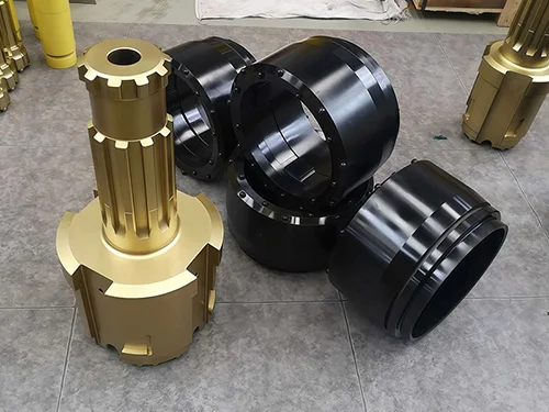
As a highly efficient drilling assembly, the system consists of the following components:
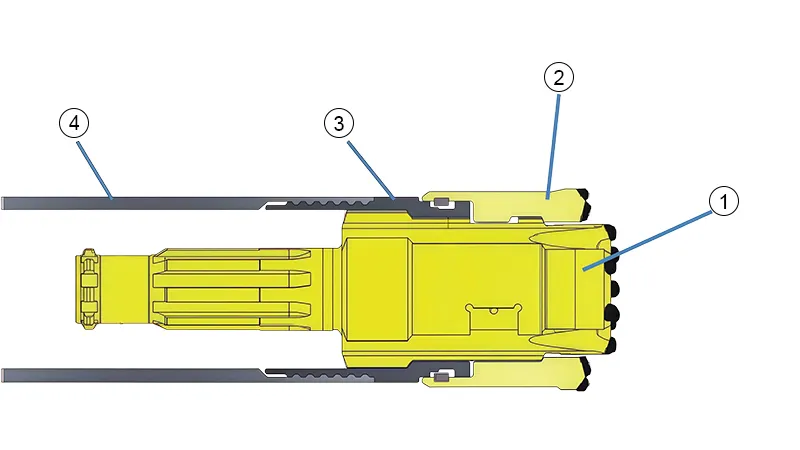
- Pilot bit
(featuring large internal flushing ports and front-facing discharge grooves) - Ring bit
(with an internal locking profile that connects to the pilot bit) - Casing shoe
(used to connect the pilot bit to the casing) - Casing
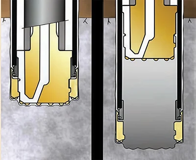
The casing shoe is welded to the casing, while the pilot bit and ring bit are locked together using a bayonet-type coupler, which uses matching slots and lugs that twist together to lock the pilot bit and ring bit securely in place. Driven by the DTH hammer, the locked pilot bit and ring bit rotate together to drill a hole sized for the casing. During drilling, the casing shoe and casing remain stationary and do not rotate with the bit. Once the target depth is reached, a slight reverse rotation unlocks the coupling, allowing the pilot bit, hammer, and drill string to be retrieved through the casing. The ring bit and casing shoe normally remain in the hole for casing support, but with special designs they can also be retrieved using the same method.
- Simple structure:
The concentric bit has no complex eccentric opening or closing mechanisms, with fewer components, lower failure rates, and easier maintenance. - High stability:
The bit maintains reliable concentricity with the casing, reducing deviation during drilling and making it suitable for applications requiring strict verticality, such as foundation piles and anchor holes.
Concentric casing systems are suitable for relatively stable formations without hard interlayers or large boulders. Typical uses include:
- Drilling cast-in-place piles in foundation construction
- Excavation support in soft soils (e.g., soil nail walls, anchor holes)
- Creating cutoff walls in hydraulic engineering
- Core drilling in geological exploration where an intact borehole wall is required
| Model | Casing OD, mm | Casing min. ID, mm | Max. wall thickness, mm | Reaming diameter, mm | Compatible DTH hammer | Max. bit pass-through diameter, mm |
| |
114 | 101 | 7 | 120 | SPM35A | 85 |
| |
127 | 108 | 9 | 135 | SPM35A | 95 |
| |
146 | 126 | 10 | 152 | SPM45A | 115 |
| |
168 | 148 | 10 | 171 | SPM55A | 140 |
| |
178 | 158 | 10 | 185 | SPM55A | 145 |
| |
183 | 163 | 10 | 191 | SPM55A | 152 |
| |
194 | 174 | 10 | 206 | SPM65A | 165 |
| |
219 | 199 | 10 | 235 | SPM65A | 185 |
| |
245 | 232 | 6.5 | 258 | SPM85A | 205 |
| |
273 | 249 | 12 | 285 | SPM85A | 220 |
| |
305 | 281 | 12 | 325 | SPMS100 | 265 |
| |
323 | 299 | 12 | 345 | SPMS100 | 279 |
| |
355 | 331 | 12 | 375 | SPM112A | 311 |
| |
406 | 381 | 12.7 | 428 | SPM112A | 350 |
| |
457 | 432 | 12.7 | 480 | SPM112A | 391 |
| |
508 | 476 | 16 | 520 | SPM112A | 420 |